
MENU
©2019 Guangzhou Aipu Electron Technology Co.,Ltd All rights reserved
Technology
资讯详情
Application of power module in "four-in-one"
Classification:
Power technology
2019/02/14
Page view:
[Abstract]:
The concept of “four-in-one” was first proposed in 2014. In 2015, the State Grid Marketing Department issued the “Notice on Accelerating the Application of Four-in-One Collection”, and released the “Typical Technical Solution for Four-in-One Collection”. For the construction of smart cities, the centralized collection of data from the four tables, that is, the convenience of the government to analyze the regional energy use ratio and the use of structural differences, also provide data support for the government to formulate policies such as energy conservation, emission reduction and efficiency improvement; Use energy information to achieve intelligent interaction; analyze energy use for enterprises and provide a more diversified service experience. In the long run, “four-in-one” is a good project that is conducive to urban development and improves people's living standards. The industrial chain has brought a new round of performance growth. As an indispensable part of the system, isolated power supply will certainly usher in a new growth point. This paper mainly introduces the “four-in-one” project for power supply. Demand
Introduction
State Grid proposed that the scale of "four-in-one collection" in 2016 will reach 3 million. At the end of the "Thirteenth Five-Year Plan" period, "four-in-one collection" reached 30 million households. At present, various enterprises have successively promoted the development of four-in-one in the pilot, and have received good results. At the same time, it also promotes the formulation of standards. At present, some of the requirements have been included in the standard rules. It is believed that in 2017, the pilot experience will be integrated and industry standards will be introduced.
1. The “four-in-one” pilot in various cities, although the programs are different, has not been fully unified for the time being, but overall, “integration” is a success. From the current different pilot schemes in various places, we can find the same point of the project's demand for power modules: demanding reliability requirements and extreme cost requirements. All power companies are actively contributing to the “four-in-one” project, providing technical and product services and support for the “four-in-one” project in the power supply segment, and providing a complete set of satisfaction for the entire project before the large-scale deployment. A power solution for market demand.
2. System composition and main functions
At present, the most common "four-in-one" solution is based on the electric meter acquisition system for centralized collection and processing. The simple system consists of Figure 1:
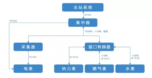
System Components:
The whole system is basically based on the meter acquisition system, so the meter information collection still maintains the status quo - the collector can communicate directly with the concentrator, or the data can be directly transmitted to the concentrator. The heat meter, gas meter and water meter information are converted by the interface converter, and then transmitted to the concentrator for information communication. The concentrator aggregates all the information and transmits it to the master system.
Among them, one master station system can include multiple concentrators, and one concentrator can manage and summarize multiple collectors and interface converters in a unified manner. Such a system configuration is the simplest scheme of the current four-in-one, and the impact on the entire information network is mainly to increase the link of the protocol conversion.
Power supply requirements:
The main change of the system is to increase the function of protocol conversion. Therefore, the demand for new power supply is mainly to supply power to various communication ports and main control systems. According to the typical interface converter interface shown in Figure 2 below, the specific power supply The requirements are as follows:
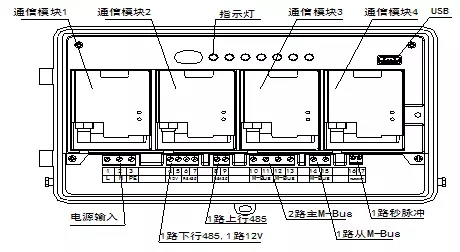
① Main control system power supply requirements: SHAPE
\* MERGEFORMAT
12V demand: Uplink communication module + downlink communication module, totaling about 3.3W.
5V demand: USB power supply requires 100mA.
3.3V demand: The main system is calculated according to 3.3V/200mA.
② Communication interface power supply requirements: SHAPE
\* MERGEFORMAT
Main M-BUS: A total of 2 channels, each with 128 meters, the power needs about 20W.
From the M-BUS: from the MBUS chip power supply from the MBUS bus, the isolated optocoupler power supply can be taken from the MBUS chip, so no additional power is required from the MBUS circuit.
2-way 485 power supply: power needs about 0.5W
External power supply 12V: The load capacity is not less than 1A. This power supply works with the main M-BUS power supply and does not work at the same time.
According to the above power supply requirements, our recommended power supply scheme is as follows.
As shown in Figure 3 above, the left side is powered by the main control system. The power supply of the MCU and the USB port is provided after the step-down of the self-bonding step-down scheme; the power supply of the uplink and downlink communication modules is directly provided by the 12V output voltage of the AC-DC power supply LO26-22D3612-04. The right side of the block diagram powers the communication interface. The power supply of the MBUS bus is directly provided by the 36V output of the AC-DC power supply LO26-22D3612-04; the 12V external output power supply is externally outputted by the self-assertion buck scheme; the power supply of the 485 communication is also provided by the 36V self-bumping step-down. . Advantages of the electric scheme
As can be seen from the scheme diagram, although there are many kinds of voltage requirements for power supply, it is mainly between the main control system and the communication interface that needs to be isolated. Therefore, the power supply we chose in the design is a 12V and 36V isolated output solution, and other places are provided by self-tapping. The isolation voltage between the output 2 channels is up to 4000VAC, and the isolation voltage of the 220VAC AC input port to the two DC output ports is up to 4500VAC. Such a solution greatly reduces the size of the power module and increases the cost performance of the entire design.